Henan yipump Pump Industry Co., Ltd. is a modern enterprise committed to designing, manufacturing and selling various multi-stage pumps, wear-resistant multi-stage pumps, vertical sewage pumps, vertical mud pumps, multi-stage centrifugal pumps, mining multi-stage centrifugal pumps, mining multi-stage pumps, horizontal multi-stage pumps and corrosion-resistant multi-stage pumps.
Henan yipump Pump Industry Co., Ltd. is a modern enterprise committed to designing, manufacturing and selling various multi-stage pumps, wear-resistant multi-stage pumps, vertical sewage pumps, vertical mud pumps, multi-stage centrifugal pumps, mining multi-stage centrifugal pumps, mining multi-stage pumps, horizontal multi-stage pumps and corrosion-resistant multi-stage pumps.
7 * 24-hour service hotline
+86 15836191545
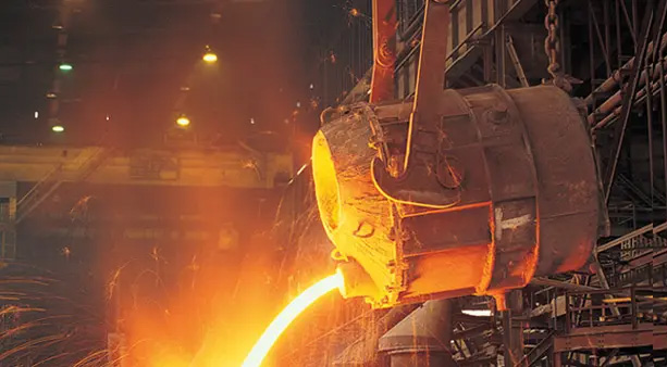
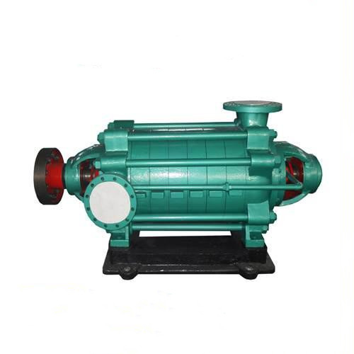
DG type pump adopts the hydraulic model of high-efficiency and energy-saving products recommended by the state. It is designed and produced in full accordance with GB / t565795 technical conditions (category) of centrifugal pump. Its type and basic parameters are designed in accordance with JB / t105193 type and basic parameters of multistage clean water centrifugal pump. The pump has the advantages of high efficiency, wide performance range, safe and stable operation, low noise, long service life, convenient installation and maintenance.
This series of pumps is suitable for medium and low pressure boiler water supply, as well as high pressure water supply and drainage in factories or cities. The temperature of the conveying medium is - 20 degrees to - 160 degrees.
Model meaning:
Example: DG 46 - 50 × four
DG - horizontal multistage boiler feed water centrifugal pump
46 refers to the design point flow of 46m3 / h
50 - indicates that the single-stage lift at the design point is 50m
4 - indicates that the level is 4
Performance range
Pump suction and discharge diameters: 40-150mm
Flow Q = 3.75-185m3 / h
Lift H = 50-684m
Technical characteristics
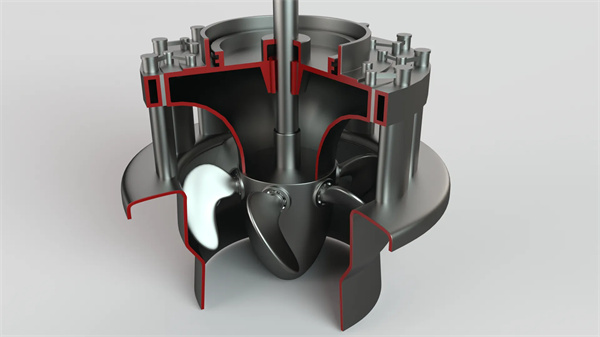
<1> New structure: with symmetrically arranged impeller rotor components, the axial forces generated by symmetrical impellers at all levels cancel each other, and the automatic balance of huge axial thrust in the pump cavity can be realized without using the balance disk structure;
<2> New technology: unique throttling and pressure reducing device, odd balance device;
<3> High efficiency: the impeller and guide vane flow passage are good for neutrality, and the efficiency will not decrease significantly with the wear of the balance disc and the forward movement of the rotor components; There is no leakage of balance water, which reduces the volume loss and improves the efficiency of the pump, which is 1% ~ 2% higher than that of the ordinary D-type pump on average;
<4> Good cavitation performance: it has good cavitation performance. The first stage impeller of some pumps adopts double suction structure;
<5> Strong reliability of the mechanical seal: there is no axial displacement of the rotor components when the pump is started and stopped, and there is no axial pulsation when the pump is working, which overcomes the problem of poor reliability of the mechanical seal that has always plagued the multistage pump;
<6> Wide application: the small gap balance disc is eliminated, which is more suitable for occasions with worse media properties than ordinary D-type pumps;
<7> High reliability: the balance disk that is easy to break down is cancelled, which greatly improves the reliability, reduces the number of maintenance times and reduces the maintenance cost;
<8> Low peak value of axial force: the axial force is only half of the ordinary D-type pump, which greatly reduces the interference effect on the pump and greatly improves the rigidity;
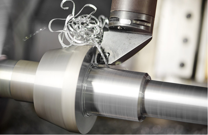
<9> Low maintenance cost: precision casting, unique throttling and pressure reducing devices are used to support the pump. The vibration and noise of the pump are greatly reduced, and the service life is long;
<10> The thermal expansion (cold contraction) of the pump is uniform and symmetrical: the thermal expansion (cold contraction) of the pump is uniform and symmetrical.
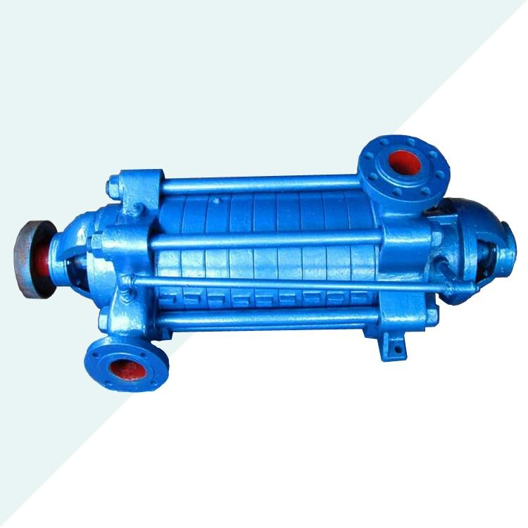
Structural features
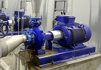
The water inlet and outlet of this type of pump are vertically upward, and the water inlet section, middle section, water outlet section, bearing body and other pump shell parts of the pump are connected together by tightening bolts. Select the number of stages of the pump according to the lift of the pump.
The rotor of this type of pump is mainly composed of the shaft and the impeller, shaft sleeve, balance disc and other parts installed on the shaft. The number of impellers is determined according to the number of stages of the pump. The parts on the shaft shall be fastened with flat keys and shaft nuts to integrate with the shaft. The whole rotor is supported by rolling bearings or sliding bearings at both ends. The bearing is determined according to different models and does not bear axial force. The axial force is balanced by the balance plate. During the operation of the pump, the rotor is allowed to move axially in the pump casing, and centripetal ball bearings are not allowed. The rolling bearing is lubricated with grease, the sliding bearing is lubricated with thin oil, and the oil ring is used for self lubrication, and the circulating water is used for cooling.
The sealing surfaces between the water inlet section, the middle section and the water outlet section of the pump are sealed with molybdenum disulfide grease. Sealing rings and guide vane sleeves are installed between the rotor part and the fixed part for sealing. When the wear degree of the sealing rings and guide vane sleeves has affected the working performance of the pump, they should be replaced.
There are two types of shaft seals: mechanical seal and packing seal. When the pump adopts packing seal, the position of packing ring shall be placed correctly, the tightness of packing must be appropriate, and the liquid can seep out drop by drop. Various sealing elements of the pump are installed in the sealing box, and water with a certain pressure should be introduced into the box for water sealing, water cooling or water lubrication. A replaceable shaft sleeve is installed at the shaft seal to protect the pump shaft.
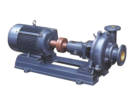
This type of pump generally adopts rolling bearing and dry oil lubrication structure. Dg85-67 and dg155-67 pumps can adopt sliding bearing, thin oil lubrication structure, rolling bearing and dry oil lubrication structure. The main parts of the pump are generally made of high-quality cast iron or cast steel or stainless steel.
This series of pumps are directly driven by the prime mover through the elastic coupling. Viewed from the direction of the prime mover, the pump rotates clockwise.
Pump assembly
The assembly sequence of the pump is generally opposite to the disassembly sequence. The assembly quality directly affects the normal operation of the pump, and affects the service life and performance parameters of the pump. Pay attention to the following points during assembly:
1. The machining accuracy and surface roughness of the parts shall be protected, and there shall be no bumps, scratches and other phenomena. The molybdenum disulfide used for sealing shall be clean, and the fastening screws and bolts shall be evenly stressed;
2. The alignment of the impeller outlet channel and the guide vane inlet channel is guaranteed by the axial size of each part. The alignment of the channel directly affects the performance of the pump, so the size of the pump cannot be adjusted at will;
3. After the pump is assembled, before the packing is installed, rotate the pump rotor manually to check whether the rotor is flexible in the pump and whether the axial displacement meets the specified requirements;
4. Press in the packing after passing the inspection, and pay attention to the relative position of the packing ring in the packing cavity.
Precautions during pump disassembly
1. Stop in the order of stopping;
2. The liquid (including cooling water) in the pump casing shall be drained; When the bearing parts are lubricated with thin oil, the lubricating oil shall be drained;
3. Remove the auxiliary pipeline that hinders the disassembly, such as the balance pipe, water seal pipe and other pipelines and leads;
4. During disassembly, the manufacturing accuracy of the parts shall be strictly protected from damage. During the disassembly of the threading rod, each middle section shall be padded with a cushion block to prevent the shaft from bending due to looseness and subsidence of the seam of each middle section.
Disassembly sequence of pump
1. After removing the pump coupling, unscrew the bolts on the bearing cap, the coupling nuts between the water inlet section and the bearing body, and then remove the front bearing body;
2. Unscrew the round nut on the shaft and remove the bearing inner race, bearing gland and retaining ring in turn;
3. Lift each middle section with a cushion block, remove the threaded nut, remove the water inlet section, and the packing gland, packing ring and packing on the water inlet section;
4. Remove the front stage impeller, the flat key, the positive guide vane, the positive impeller, the final stage positive guide vane, the outlet section, the intermediate throttling and pressure reducing device in sequence;
5. Remove the last stage reverse guide vane, the last stage reverse impeller, the flat key, the reverse guide vane, the reverse impeller, the rear throttling and pressure reducing device in sequence, and pay attention to the direction and sequence of the forward and reverse impellers and guide vanes;
6. Screw the nuts between the water inlet section and tail cover of the next stage, and remove the main shaft, tail cover and rear bearing body;
7. Unscrew the nuts between the tail cover and the bearing body, and remove the packing gland, packing ring and packing on the tail cover;
8. Unscrew the bolts on the rear bearing cover, and remove the bearing, small round nut and bearing cover in turn;
9. For pumps with sliding bearings, the disassembly sequence is basically the same, except for the slightly different disassembly of bearing components.
Installation of pump
In addition to meeting the general requirements, the following points shall be noted during the installation of this type of pump:
1. The foundation plane where the pump is installed shall be leveled with a level. After the foundation cement is set, check whether the base and anchor bolt holes are loose;
2. After the motor, pump and base are assembled, the concentricity of the pump shaft and motor shaft shall be strictly checked to ensure that the centerlines of the two shafts are on the same axis;
3. When the motor and the water pump are assembled, ensure that the axial clearance between the end faces of the two couplings of the pump and the motor is 3mm, and the series of pumps have no axial displacement;
4. The pump can only bear its own internal force, not any external force, so the suction pipeline and the discharge pipeline of the pump should have their own supports to avoid crushing the pump.
Start, operation and shutdown of pump
start-up
1) Before starting the pump, rotate the pump rotor to check whether the rotor is flexible;
2) Check whether the rotation direction of the motor is consistent with that of the pump;
3) Open the pump suction valve (if equipped), close the gate valve of the pump outlet pipeline and the cock of the pressure gauge to fill the pump with liquid, or use the vacuum system to exhaust the air in the suction pipeline and pump;
4) Check the tightness of the connecting bolts between the pump and the motor and the safety around the pump, so that the pump is ready to start;
5) Start the motor. After the pump operates normally, open the cock of the pressure gauge and slowly open the gate valve at the outlet of the pump until the pointer of the pressure gauge points to the required pressure (control the given lift of the pump according to the reading of the outlet pressure gauge).
function
1) The axial force of the pump is balanced by the pump itself, so there is no balance water pipe; To ensure the normal operation of the pump, the return pipe shall not be blocked;
2) In the process of start-up and operation, it is necessary to observe the instrument readings, bearing temperature, packing water leakage and temperature, as well as the vibration and sound of the pump. If any abnormality is found, it should be handled in time;
3) The change of bearing temperature rise reflects the assembly quality of the pump. The bearing temperature rise shall not be higher than the ambient temperature by 35 ℃, and the higher temperature of the bearing shall not be higher than 75 ℃;
4) During the operation of the pump, the wear of the impeller, seal ring, guide vane sleeve, shaft sleeve, throttling device, pressure reducing device and other parts shall be checked regularly. If the wear is too large, it shall be replaced in time.
Shut down
1) Before shutdown, close the cock of the pressure gauge, slowly close the outlet gate valve, stop the motor after the outlet valve is closed, and then close the suction valve of the pump after the pump stops stably (if equipped);
2) If the pump is out of service for a long time, remove the drain plugs under the water inlet section, water outlet section and secondary water inlet section of the pump, drain the remaining water, disassemble the pump, clean and oil it, and pack it for storage.
working principle
The impeller rotates under the drive of the motor through the pump shaft to work on the liquid and increase its energy, so that the required amount of liquid can be continuously sent out through the horizontal outlets of the pump's inlet section, positive impeller, positive guide vane, middle section, outlet section, transition pipe, secondary inlet section, reverse guide vane and vertical outlets of the outlet section.
Advantages: high efficiency, energy saving, high efficiency, wide performance range, safe and stable operation, low noise, long service life, convenient installation and maintenance.
Hundreds of customers to choose from


Add: Fengqiu County,Zhaogang Town,Xinxiang City,Henan Province,China.
Mall: sales@hnybpumps.com
Tel: +86 (0)379 63221987
Phone:+86 15836191545 (Wechat Same Number)
Wechat: HNYB-Regan
WHATSAPP:+86 15836191545