7 * 24-hour service hotline
+86 15836191545
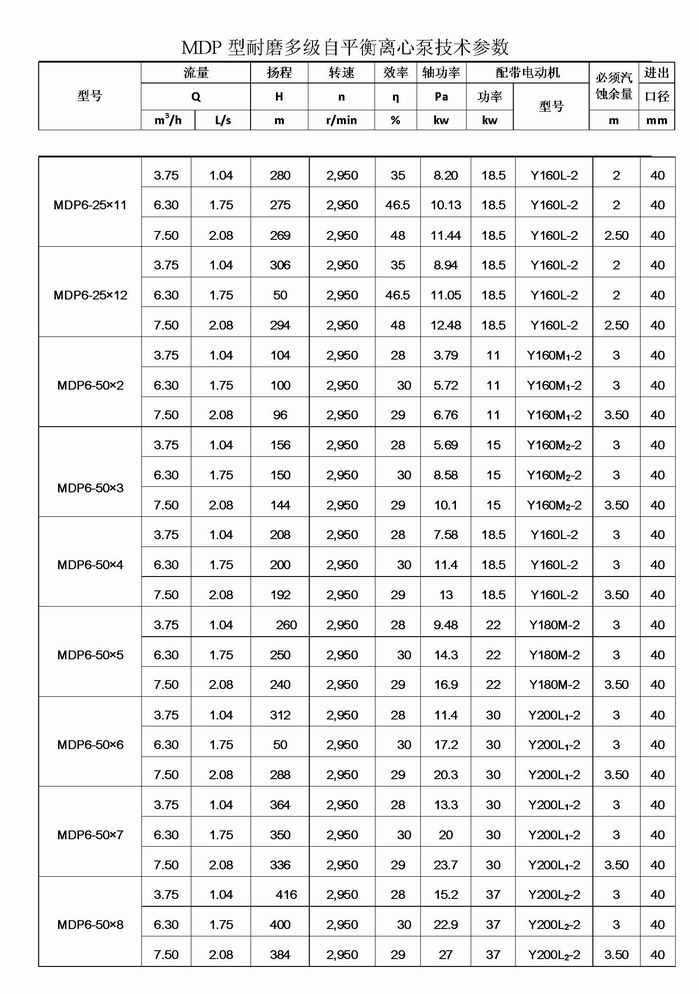
1、 Product Overview
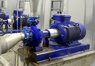
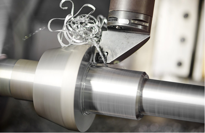
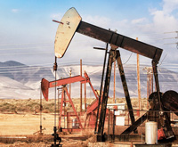
MD (P) balanced wear-resistant multistage centrifugal pump for coal mine is successfully developed by our company on the basis of introducing, digesting and absorbing advanced technology. The product has high efficiency, good cavitation performance and stable and reliable operation. It is suitable for transporting neutral mine water and other similar sewage with solid particle content no more than 1.5% (particle size less than 0.5mm) and temperature no more than 40 ℃ in coal, mines, factories and other places.
2、 Model meaning
MD100—80 × 8 (P) MD: Wear resistant multi-stage centrifugal pump for coal mine
100: flow 100m3/h
80: Single stage lift 80m
8: Series
(P) : Balanced
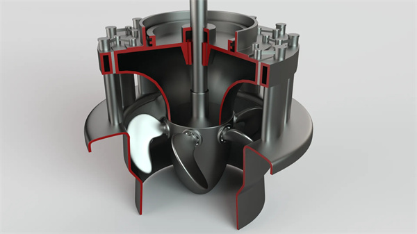
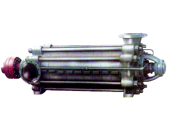
3、 Structural drawing
1. MD (P) type pump is a horizontal single suction multistage segmented centrifugal pump. Its suction inlet is located vertically upward on the forward water section. It can also be changed to a horizontal position according to the actual use needs. The outlet section is in the middle of the whole pump, and the outlet is vertically upward on the outlet section. The connecting frame, forward water section, middle section, outlet section, and rear inlet section of the pump are connected together with tension bolts. The lift can be increased or decreased according to the use needs.
2. Structure and working principle of main components
⑴ Main parts of water pump: forward water section, outlet water section, rear water inlet section, guide vane, right guide vane, left guide vane of outlet water section, right guide vane of outlet water section, middle section, impeller, right impeller, shaft, balance drum, front positioning sleeve, rear positioning sleeve, connecting frame, reversing flow passage, etc; The rotor is composed of impeller mounted on the shaft, right impeller, balance drum, impeller retaining sleeve, front locating sleeve, rear locating sleeve and other parts. The driving end of the rotor is supported by a roller bearing, and the end is arranged face to face with a diagonal contact ball bearing. The bearing is lubricated with grease.
(2) The working chamber of the pump is formed by the forward water section, the rear water inlet section, the middle section, the guide vane, the right guide vane, the left guide vane of the outlet section, the right guide vane of the outlet section, the reversing flow passage and the outlet section. The liquid enters along the axial direction unilaterally. When working, the axial force acting on each pair of symmetrically arranged impellers is opposite, which can offset each other, so that the generated axial force is balanced. Low pressure stages are arranged at both ends to reduce the pressure borne by the shaft seal.
(3) ① Shaft seal: soft packing shall be used for sealing, and the tightness of the packing must be appropriate, so that the liquid can seep out drop by drop.
② Drive: the pump is directly driven by the motor through the elastic coupling; Seen from the motor, the pump rotates clockwise.
③ Bearing: the driving end adopts roller bearing, and the end adopts a diagonal contact ball bearing.
④ Sealing ring: prevent the high-pressure water in the water pump from leaking back to the water inlet, and replace it after wear.
⑤ Balance drum: it is installed behind the last stage impeller and rotates with the rotor to form a radial clearance between the outer circle surface of the balance drum and the inner hole surface of the balance sleeve.
⑥ Front and rear locating sleeves: at the two packing chambers, they can be replaced after wear.
(4) Working principle: the pump shaft rotates under the drive of the motor to work on the liquid and increase its energy, so that the required amount of liquid is sent from the suction tank to the required high place or the required pressure place through the pump's overflow parts.
Hundreds of customers to choose from


Add: Fengqiu County,Zhaogang Town,Xinxiang City,Henan Province,China.
Mall: sales@hnybpumps.com
Tel: +86 (0)379 63221987
Phone:+86 15836191545 (Wechat Same Number)
Wechat: HNYB-Regan
WHATSAPP:+86 15836191545