7 * 24-hour service hotline
+86 15836191545
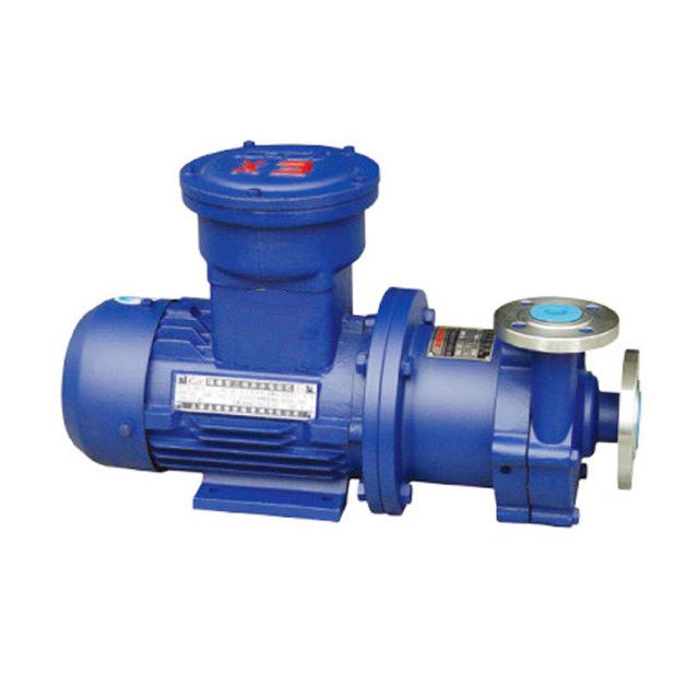
1、 Product Overview
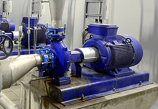
MD wear-resistant multistage centrifugal pump is a wear-resistant multistage centrifugal pump modified and designed by our company on the basis of D type single suction multistage clean water centrifugal pump. MD wear-resistant multistage centrifugal pump, featuring high efficiency, energy saving, wear resistance, reliability and long service life, is especially suitable for mine drainage. It pumps mine water and other similar liquids with solid particle content no more than 1.5% (particle diameter less than 0.5mm), and the liquid temperature is no higher than 80 degrees.
2、 Model meaning
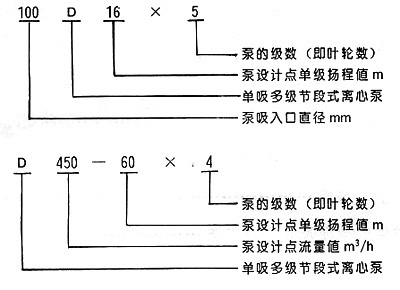
Note: D (DF multistage corrosion-resistant centrifugal pump, DY multistage centrifugal oil pump, MD multistage wear-resistant centrifugal pump) 80-30 is the customary expression method, in which 80 means the diameter of the pump suction inlet is 80mm, 30 means the single stage head at the pump design point is 30m, and other meanings are the same as those above.
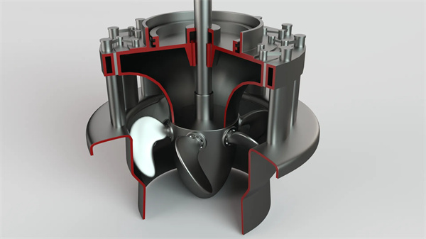
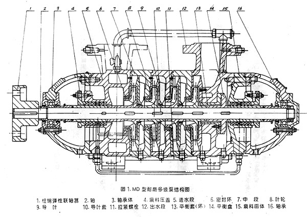
3、 Structural drawing
4、 Technical characteristics
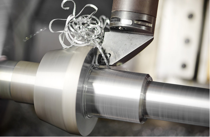
High efficiency and energy saving: Adhere to the * * * production, and have unique methods for product model selection, mold making, and casting process of hydraulic components. All flow passage components are precision cast to ensure the size and finish of the flow passage, which is more than 2% higher than the measured efficiency of ordinary multi-stage pumps on the market, and has a good energy saving effect.
Advanced process equipment: In order to ensure the assembly performance of products, our company has imported advanced parts cleaning equipment from abroad. Each part is carefully cleaned before final assembly to ensure the assembly quality of products.
Unique structure: O-ring is added on the matching surface of the balance ring and the pump to prevent high-pressure water from entering the balance chamber, reduce the wear of the balance plate, and extend the service life of the product. For pumps with a diameter of more than DN200, a balance disc wear indicator shall be set at the shaft end to observe the wear at any time, and the balance disc or balance ring shall be replaced in time to ensure the normal operation of the equipment.
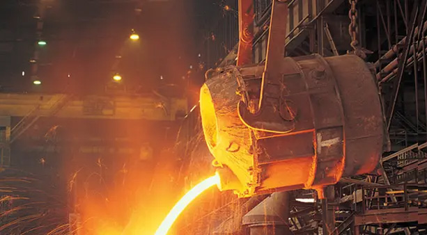
Reasonable material selection: the materials of balance disc and balance ring can be hardfacing cemented carbide, alloy steel or QT600Mn2 alloy ductile cast iron according to the needs of different users, with high surface hardness, good wear resistance and improved product service life. The flow passage of MD type pump is made of high alloy wear-resistant cast iron or high-grade wear-resistant ductile iron, which has good wear resistance.
Good surface quality: precision casting process and automatic spraying machine are used to spray paint, with good surface quality and beautiful appearance.
5、 Structural characteristics
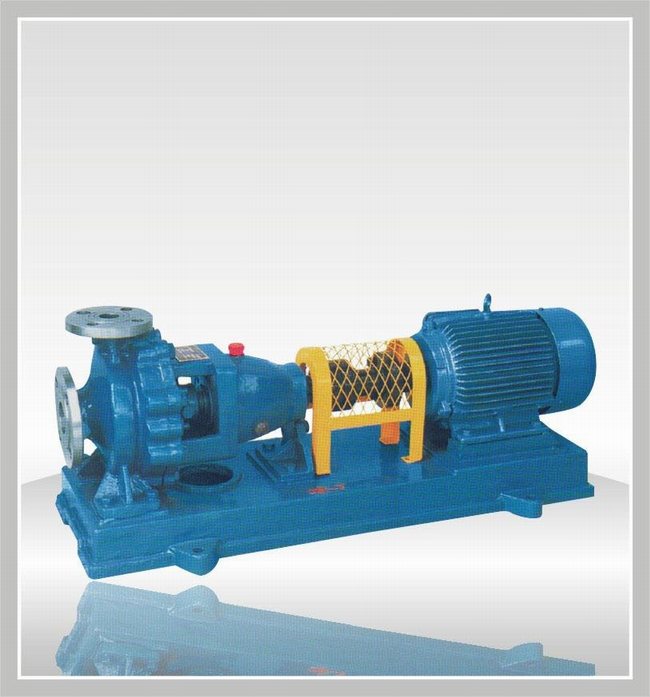
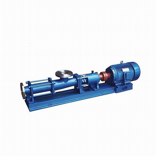
MD series pump is a horizontal, single suction, segmented multi-stage centrifugal pump. The suction port is horizontal, and the discharge port is vertical to the horizontal. The inlet section, middle section, outlet section of the pump and the part of the bearing housing to be pumped are connected into one by tightening bolts, and the pump stages are selected according to the pump head.
The rotor part of this series of pumps is mainly composed of the shaft and the impeller, shaft sleeve, balance plate and other parts installed on the shaft. The number of impellers depends on the pump stage. The parts on the shaft are fastened with flat keys and shaft nuts to make them integrated with the shaft. The whole rotor is supported by rolling bearings or sliding bearings at both ends. The bearings are determined according to different models and do not bear axial force. The axial force is balanced by the balance plate. During the operation of the pump, the rotor is allowed to swim axially in the pump casing, and the centripetal ball bearing cannot be used. The rolling bearing is lubricated with grease, and the sliding bearing is lubricated with thin oil, self lubricated with oil ring, and cooled with circulating water.
The sealing surfaces between the inlet section, middle section and outlet section of the pump are sealed with molybdenum disulfide grease. The sealing ring and guide vane sleeve are installed between the rotor part and the fixed part for sealing. When the wear of the sealing ring and guide vane sleeve has affected the working performance of the pump, they should be replaced.
There are two types of shaft seals: mechanical seal and packing seal. When the pump adopts the packing seal, the position of the packing ring should be correct, the tightness of the packing must be appropriate, and it is appropriate that the liquid can seep out drop by drop. All kinds of sealing elements of the pump are installed in the sealing cavity, and the cavity should be filled with water under a certain pressure. The water seal, water cooling or water lubrication are allowed. A replaceable shaft sleeve is installed at the shaft seal to protect the pump shaft.
From the direction of the original motor, the pump rotates clockwise.
In addition, our company can realize the structure and function of multiple outlets of this series of pumps according to user needs.
6、 Installation and removal
Assembly and disassembly of pump
(1) Precautions for pump disassembly
1. Stop according to the parking sequence;
2. The liquid (including cooling water) in the pump casing shall be drained; When the bearing parts are lubricated with thin oil, the lubricating oil shall be drained;
3. Remove the auxiliary pipelines, such as balance pipe, water seal pipe and other pipelines and leads that hinder disassembly;
4. During disassembly, the manufacturing accuracy of the parts shall be strictly protected from damage. When disassembling the threading rod, each middle section shall be padded with a cushion block to prevent the shaft from bending due to looseness and sinking of each middle section's spigot.
(2) Disassembly sequence of pump
1. Unscrew the bolts on the bearing end cover at the discharge side and the connecting bolts between the water outlet section, tail cover and bearing body, and remove the bearing end cover, bearing body and other bearing parts;
2. Unscrew the round nut on the shaft and remove the bearing inner ring, bearing gland and retaining ring in turn, and then remove the packing body (including the packing gland, packing ring, packing, etc.);
3. Remove the O-ring, shaft sleeve, balance disc and key on the shaft in turn, and then remove the outlet section, end guide vane, balance ring sleeve, etc;
4. After removing the last stage impeller and key, remove the middle section and guide vane; Remove the impellers at all levels, the middle section and the guide vanes in turn until the front stage impeller is removed;
5. After removing the pump coupling, unscrew the connecting nuts of the water inlet section and the bearing body and the bolts on the bearing gland, and then remove the bearing components at the water inlet section side;
6. Extract the shaft from the water inlet section, unscrew the fixed nut on the shaft, and then remove the bearing inner ring, O-ring, shaft sleeve, etc. in turn;
7. For the pump with sliding bearing, the disassembly sequence is basically the same, only slightly different when disassembling the bearing components.
(3) Assembly of pump
The pump is generally assembled in the opposite direction of the disassembly sequence. The quality of assembly directly affects the normal operation, service life and performance parameters of the pump. Pay attention to the following points during assembly:
1. The processing accuracy and surface roughness of the parts shall be well protected, and there shall be no bumps, scratches, etc. The molybdenum disulfide used for sealing shall be clean, and the fastening screws and bolts shall be evenly stressed;
2. The centricity of impeller outlet channel and guide vane inlet channel is ensured by the axial size of each part. The centricity of the channel directly affects the performance of the pump, so the size of the pump cannot be adjusted at will;
3. After the pump is assembled and before the packing is installed, rotate the pump rotor by hand to check whether the rotor is flexible in the pump and whether the axial displacement meets the specified requirements;
4. After passing the inspection, press the packing, and pay attention to the relative position of the packing ring in the packing chamber.
Hundreds of customers to choose from


Add: Fengqiu County,Zhaogang Town,Xinxiang City,Henan Province,China.
Mall: sales@hnybpumps.com
Tel: +86 (0)379 63221987
Phone:+86 15836191545 (Wechat Same Number)
Wechat: HNYB-Regan
WHATSAPP:+86 15836191545