7 * 24-hour service hotline
+86 15836191545
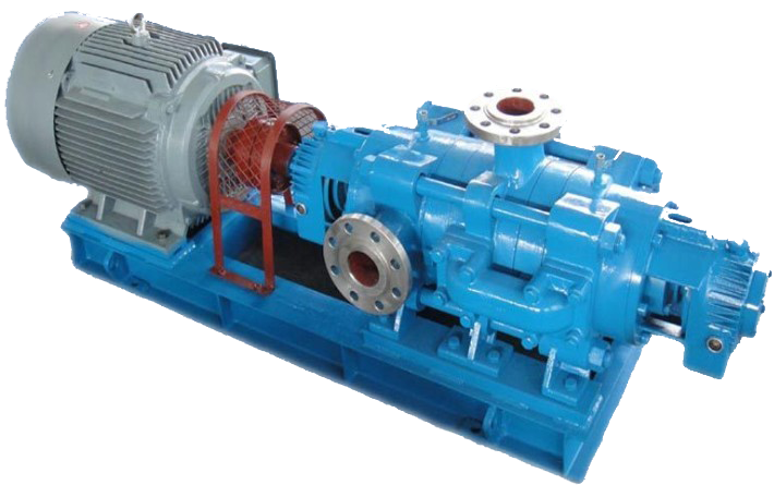
1、 Product Overview
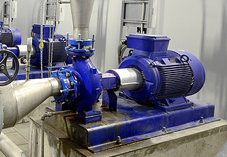
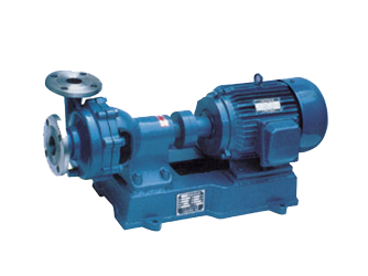
BA type pump series single-stage single suction cantilever centrifugal pump is used for suction and delivery of clean water and liquids with physical and chemical properties similar to water.
When the lift of this type of pump is 8-93m and the flow is 4.5-360m3/, the higher temperature of the liquid shall not exceed 80 ℃, which is suitable for factory, mine, urban water supply and farmland irrigation.
2、 Structure description
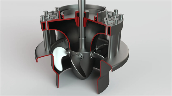
The other main components of BA type pump are: pump body (1); Pump cover (2) 'impeller (3); Shaft (4); And bracket (5). The discharge outlet of the pump is perpendicular to the axis of the pump, and can rotate 90 ° with the pump body according to the installation and use conditions., l80。 And 270. Corner. This type of pump is directly rotated by the motor through the elastic coupling, or by the belt transmission device.
Figure 1 shows the longitudinal sectional structure of the BA type water pump. Both ends of the shaft are supported by single row radial ball bearings and lubricated with thin oil.
Figure 2 represents the outline drawing of l6 types of BA pumps. Figure 3 is the installation drawing of BA pumps. The overall dimensions and installation dimensions of BA pumps are attached below.
The pump body (1) is made of cast iron, which is internally provided with a vortex shaped flow passage that gradually diffuses to the pump outlet, and the outlet flange is drilled with a pipe screw hole for installing a pressure gauge.
The pump cover (2) is made of cast iron, the flow channel is contractive, and there is a paper pad between it and the pump body. The water inlet flange is drilled with a pipe screw hole for installing a vacuum gauge.
Impeller (3) is made of cast iron, with unilateral water inlet and curved blade inside. Several holes are drilled near the shaft hole to balance the axial force, but 11/2BA-6, 2BA-6, 2BA-9, 3BA-9, 3BA-13, 4BA-18, 4BA-25. The impeller is not drilled and bears the axial force relying on the bearing. During manufacturing, it passes the static balance test.
The shaft (4) is made of high-quality carbon steel. One end of the shaft is fixed with the impeller. During operation, the shaft is assembled in the ball bearing in the bracket and rotates.
The bracket (5) is made of cast iron. The bracket lubricated with thin oil has an oil chamber. The oil level should always be measured with an oil dipstick.
The packing plays a sealing role to prevent air penetration and large amount of liquid seepage. The packing seal is composed of packing chamber, packing gland, packing ring and lead powder oil immersed asbestos rope. A small amount of high-pressure liquid flows into the packing chamber through the flushing hole in the pump body to play the role of water seal. The tightness of the packing must be appropriate, neither too tight nor too loose. The liquid can seep out one drop at a time. If the packing is too tight, the shaft is easy to heat up, and the power is consumed at the same time, the packing is too loose, and the liquid leakage is large, reducing the efficiency of the water pump. If there is too much water in the packing, the packing should be filled or replaced on time.
The water pump and motor are installed on a base and connected with an elastic coupling. When installing, it must be noted that the motor and pump shafts are on the same centerline.
3、 Installation, starting, stopping and running
1. Installation:
(1) Preparations before installation;
A. Check the water pump and motor for damage.
B. Prepare tools and lifting appliances.
C. Check the installed foundation according to the drawing.
(2) Installation sequence:
A. When the complete set of water pump arrives at the site, the motor has been installed with the base. It is unnecessary to remove the water pump and motor when leveling the base.
B. Place the base on the foundation, pad the iron near the anchor screws, pad the base up about 20-40mm, and prepare to fill the cement slurry after leveling.
C. Check the levelness of the pump base with a level gauge. After leveling, tighten the anchor screws and nuts, and pour the pump base and anchor screw holes with cement slurry.
D. After 3 to 4 days of cement drying, check the primary water levelness.
E. Clean the supporting plane of the pump base, the plane of the pump foot and the motor foot, and place the pump and motor on the base.
F. Adjust the level of the pump shaft. After leveling, tighten the nut properly to prevent starting. After the adjustment of the pump end is completed, install the motor, and pad the base plate on the foot with improper level. Leave a certain clearance between the pump and motor coupling (see Fig. 3 Installation Drawing).
G. Place the steel ruler on the coupling, and check whether the axis line of the water pump coincides with the axis line of the motor. If not, put a few thin iron sheets at the foot of the motor to make the motor coupling conform to the steel ruler. When several thin iron sheets are used, take them out, replace the same thickness with a planed whole pad, and recheck the installation.
In order to check the installation accuracy, use a feeler gauge to measure the gap between the coupling planes at several opposite positions. The gap between the planes at both ends of the coupling is larger and smaller around the circumference. The difference should not exceed 0.3mm. The difference between the lower or left and right sides of the centerline at both ends should not exceed 0.1mm.
2. Start and stop:
(1) Check the grease in the bracket or measure whether the oil level of the thin oil is within the specified range with an oil dipstick.
(2) Start the test and check whether the rotation direction of the motor is correct. The test time shall not exceed 1 minute.
(3) Fill the water pump and suction pipe through the screw hole on the upper part of the pump body.
(4) Close the valve on the discharge pipe and the cock of the pressure gauge.
(5) After the above process is completed, start the motor and open the pressure gauge cock.
(6) When the water pump operates at full speed, the pressure gauge will display appropriate pressure, then open the vacuum gauge cock, and gradually open the gate valve on the drainage pipeline to the required range.
(7) When stopping the water pump, slowly close the gate valve on the drainage pipeline, close the vacuum gauge cock, stop the motor, and then close the pressure gauge cock.
If the environment and outside temperature are low, open the square screw plug at the lower part of the pump body to drain the water in the pump to avoid frost cracking.
(8) When the water pump is not used for a long time, the water pump shall be disassembled, the water on the other part shall be wiped dry, and the sliding surface shall be coated with anti rust oil for proper storage.
3. Operation:
(1) Pay attention to the bearing temperature of the water pump, which should not exceed the external temperature by 35 ℃, but should not be higher than 75 ℃.
(2) The oil level in the bracket must be kept between the two scales of the oil dipstick.
(3) Within * * * months of the operation of the water pump, the lubricating oil of the bracket shall be replaced after 100 hours. After that, the thin oil shall be replaced every 500 hours of the operation of the water pump, and the grease shall be replaced every 2000 hours.
(4) The normal degree of water leakage in the packing chamber is 10-20 drops per minute. If it exceeds or is too small, the packing gland should be compressed or loosened.
(5) Regularly check the elastic coupling and pay attention to the temperature rise of motor bearing.
(6) In case of any noise or unusual sound during operation, stop immediately and check the cause.
(7) Periodical inspection shall be carried out every 2000 hours when the pump runs. The clearance between the impeller and the seal ring shall not be excessively worn. For pumps with a suction diameter of 100mm or less, the larger value of the clearance in the diameter direction is 1 • 5mm. For pumps with a suction pipe diameter of 100mm or more, the larger value of the clearance in the diameter direction is 2mm. If the diameter of the suction pipe is 100mm or more, the seal ring can be replaced.
Hundreds of customers to choose from


Add: Fengqiu County,Zhaogang Town,Xinxiang City,Henan Province,China.
Mall: sales@hnybpumps.com
Tel: +86 (0)379 63221987
Phone:+86 15836191545 (Wechat Same Number)
Wechat: HNYB-Regan
WHATSAPP:+86 15836191545