7 * 24-hour service hotline
+86 15836191545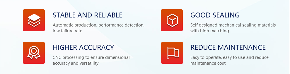
1、 Product Overview
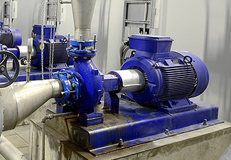
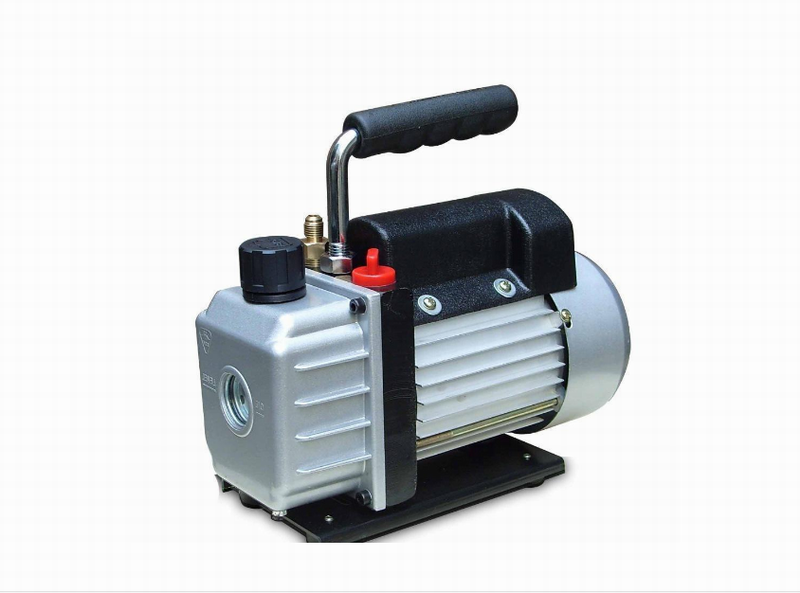
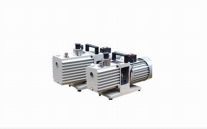
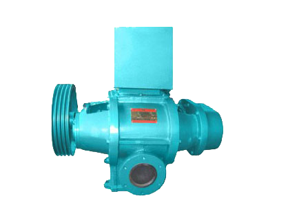
SK series water ring vacuum pump and compressor are used to pump or press gas and other non corrosive, water-insoluble and solid particle free gases, so as to form vacuum or pressure in closed containers and meet the requirements of process flow. A small amount of liquid is allowed to be mixed in the inhaled or compressed gas.
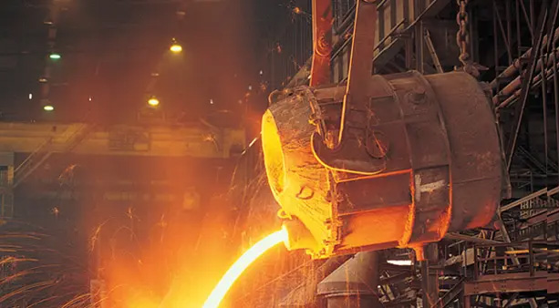
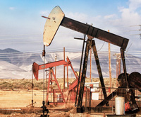
SK series water ring vacuum pumps and compressors are widely used in machinery, petroleum, chemical, pharmaceutical, ceramics, sugar, printing and dyeing, metallurgy, electronics and other industries. Because the gas compression of this type of pump is carried out under the isothermal state in the working process, it is not easy to cause danger when pressing or pumping flammable and explosive gas, so it is more widely used.
2、 Model meaning
3、 Structural drawing
4、 Technical characteristics
5、 Structural characteristics
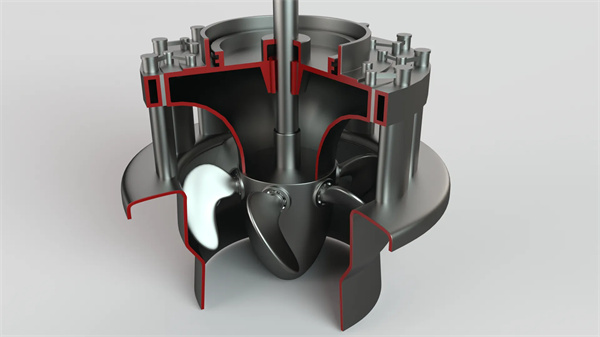
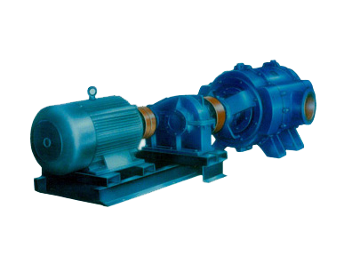
The pump is composed of pump body, two end covers, impeller, shaft and other components. The intake and exhaust bamboos are connected with the pump chamber through the suction hole and sample hole on the disc mounted on the end cover. The shaft is eccentrically mounted in the pump body, and the impeller is fixed on the shaft with a flat key. The total clearance at both ends of the pump is adjusted by the pad between the pump body and the disc. The clearance between the impeller and the disc on the end cover is adjusted by the impeller driven by the shaft sleeve (SK-1.5/3/6) or back cap (SK-12/20/30), The shaft above SK-42 and the impeller are interference fit. This clearance is determined by the front end positioning. SK-42-60-85-120 has no shaft sleeve, and the other structures are the same as SK-6/12/20/30. The clearance between the two end faces of the impeller and the end cover disc determines the loss of gas in the pump cavity from the air inlet to the exhaust port and its limit pressure.
The packing is installed in the covers at both ends. The sealing water enters the packing through the holes in the end cover to cool the packing and strengthen the sealing effect. The make-up water required for the impeller to form the water ring is supplied by the water supply pipe, which can be connected with the gas water separator for circulating water supply.
The mechanical seal is adopted as the sealing form. The mechanical seal is installed in the packing cavity, and the packing is omitted. The packing gland is replaced with a mechanical seal gland, and the other structures are the same.
The bearing is fixed on the shaft by round nut,
A disc is installed on the end cover. The disc is equipped with suction holes, exhaust holes and rubber ball valves to discharge the gas before the exhaust port when the gas pressure between the impeller blades reaches the exhaust pressure, reducing the power consumption due to excessive gas pressure, thereby reducing the power consumption.
6、 Installation and removal
disassemble:
The disassembly of the pump is divided into partial disassembly inspection, complete disassembly repair and replacement of parts. Before disassembly, the water in the pump chamber shall be drained Remove the air inlet and exhaust. During disassembly, all pads shall be carefully removed. In case of damage, new pads of the same thickness shall be more abstract during assembly. The pump shall be disassembled from the rear end (the end without coupling) in the following order:
1 Loosen and remove the two connecting pipes (SK-1.5/3 has no connecting pipe);
2 Loosen and remove the rear bearing gland;
3 Loosen the round nut with hook wrench and take down the packing gland;
4 Loosen the packing gland nuts and remove the packing gland:
5 Loosen the connecting bolts between the pump body and the end cover and the accumulated bolts at the pump foot;
6 Add a support under the pump body, and then remove the end cover from the shaft;
7 Remove the pump body. The pump has been disassembled until now, and the working part of the pump and all incoming parts can be inspected and cleaned. Complete disassembly shall be carried out in the following order:;
8 Loosen the other pump foot bolt and remove the pump head from the base;
9 Remove the coupling
10 Remove the key of the coupling from the shaft
11 Remove the front bearing gland;
12 Loosen the bearing backup cap and take down the bearing frame and bearing;
13 Loosen the compression nut of the packing gland and take down the packing gland;
14 Take out the shaft and blade from the end cover together;
15 Remove the shaft sleeve from the shaft;
16 Take the impeller from the shaft.
After disassembly, the mating surface and thread shall be carefully wiped and coated with engine oil.
Assembly:
① Before assembly, clean the gasket left on the mating surface and carefully wipe it:
② Clean the old oil in the bearing and bearing frame and replace with new oil:
③ The assembly sequence is reverse to the disassembly sequence.
During assembly, the main thing is to adjust the clearance between the impeller end face and the disc on the end cover. The size of the clearance directly affects the performance of the pump. The total clearance between the two sides is specified in the following table, which is obtained by padding between the pump body and the end cover. The clearance between the two ends of the impeller should be uniform, and it can be adjusted by loosening and tightening the shaft sleeve or back cap to move the impeller.
Hundreds of customers to choose from


Add: Fengqiu County,Zhaogang Town,Xinxiang City,Henan Province,China.
Mall: sales@hnybpumps.com
Tel: +86 (0)379 63221987
Phone:+86 15836191545 (Wechat Same Number)
Wechat: HNYB-Regan
WHATSAPP:+86 15836191545